
By Jeff Nazzaro, product manager for gearheads and motors Electromechanical and Drives Division North America
Parker Hannifin Corporation
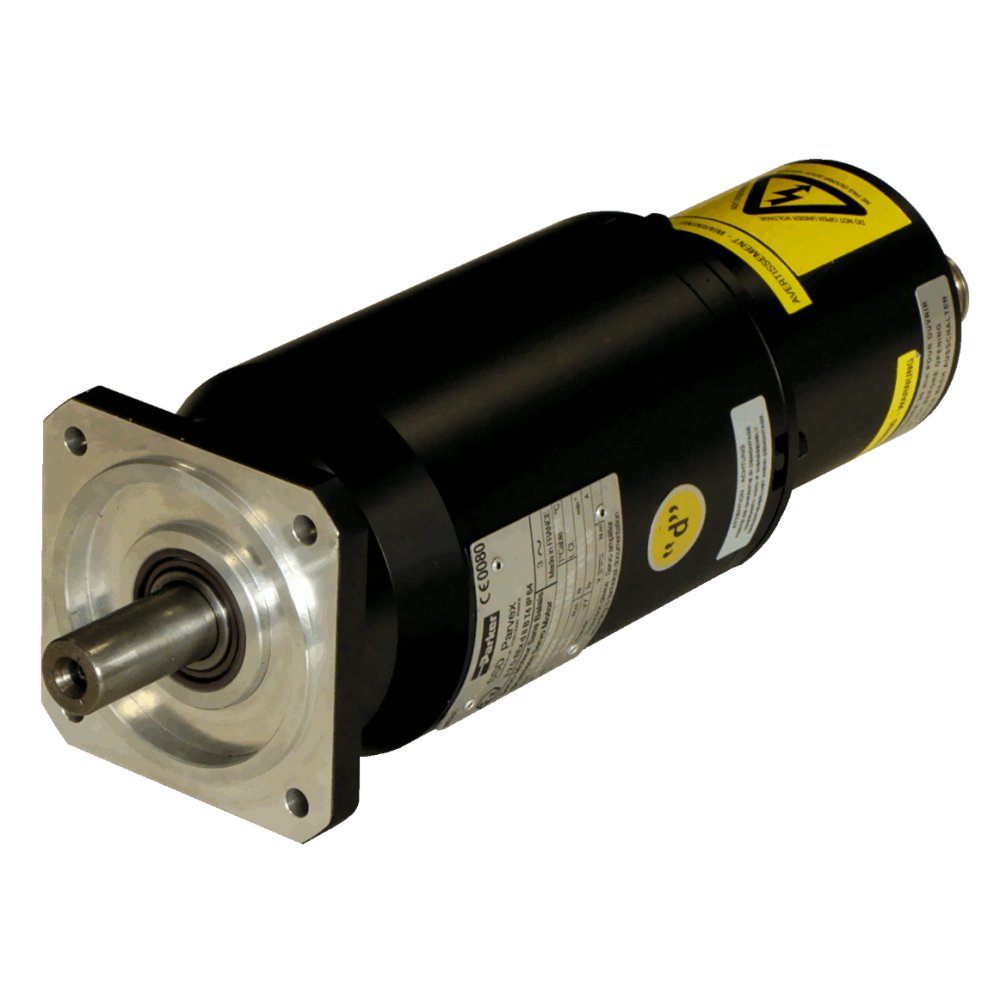
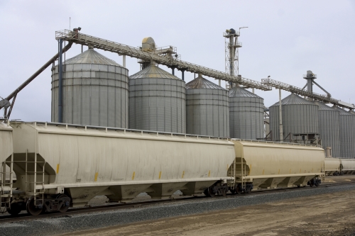 Hazardous locations are operating environments in which explosive or ignitable vapors or dust are present, or are likely to become present. It is normal for various processing applications where gas, liquid or dust will be present in enough volume to cause an opportunity for them to ignite and cause a fire and/or explosion. An example would be an automated paint spray booth where the vapors in the air would ignite from a spark, or from a motor’s surface temperature that was too hot. In such environments, special motors are needed to ensure that any internal fault in the motor will not ignite, or be a source of an ignition.
A risk assessment must be taken to classify potentially dangerous locations as hazardous environments. Equipment and materials must also be suited for use in these dangerous areas. Learning the commonly used terms and design criteria used to qualify equipment will simplify your specification process.
This is important to know and understand so that if your processes are defined as creating a hazardous environment, you can take the steps necessary to specify the correct equipment into your facility that will not create the potential for people to be injured or killed; or for damages to occur from using this equipment.
What are explosion proof requirements for motors?
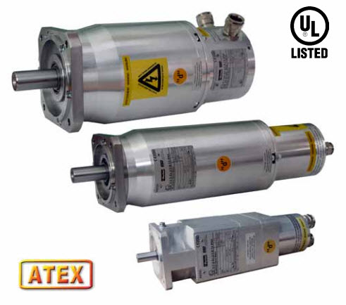
 Explosion proof requirements for servo motors are dictated in the United States by UL674 and in Europe under the acronym of ATEX. The following provides definition to the terms that are commonly used within each of the directives. Thereafter, information on the design criteria used to qualify equipment for use in these hazardous areas.
UL674
Under UL674 directive, hazardous locations are those areas where fire or explosion hazards may exist due to the presence of substances that are flammable, combustible, or ignitable. These locations break into classes and divisions and further defined by groups and temperature classifications.
Class definitions
Class I – created by the presence of flammable gases or vapors in the air, or flammable liquids, in sufficient quantities to be explosive or ignitable. Class I locations are further categorized by Division (Refer to chart 1) and fall into Group A through D. (Refer to chart 2).
Class II – created by the presence of combustible dust, suspended in the air, in sufficient quantities to be explosive or ignitable. Class II locations are further categorized by Division (Refer to chart 1) and fall into Group E through G. (Refer to chart 3).
Class III – areas, where there are easily ignitable fibers or flyings, are present. These include cotton lint, flax, and rayon as examples. The fibers in a Class III area are not likely to be in the air but can collect around machinery or on lighting fixtures. A Class III location can be categorized as Division 1 or 2.

Chart 2: Gas, vapor, and liquid groups
Relate to the Minimum Ignition Energy of the flammable substance and the location where it is installed. The lower the ignition energy required to ignite the gas, the more dangerous the environment.

Chart 3: Dust groups

Temperature classification – “T-Codes”
The surface temperature or any part of the electrical equipment that may be exposed to the hazardous atmosphere should be tested so that it does not exceed 80% of the auto-ignition temperature of the specific gas, vapor or dust in the area where the equipment is intended to be used.
The temperature classification on the electrical equipment label will be one of the following (in degrees Celsius):

ATEX
ATEX consists of two European (EU) directives. They are:
Zones – Broken into gas and dust groups. Zones 0, 1, and 2 relate to gas, and zones 20, 21, and 22 relate to dust.
Equipment Groups – Broken into group I and II and further broken down by category. The category definition is based on equipment design for protection.
Group I – Intended for use in underground mines as well as those parts of surface installations of such mines that are endangered by fire and/or combustible dust.
• Category M1 – ensures a very high level of protection.
• Category M2 – ensures a high level of protection.
Group II – Intended for use in surface equipment that is, or can be exposed to hazardous conditions (fire or explosion).
• Category 1 – ensures a very high level of protection against gas, vapor, mists, and dust that are present continuously, frequently, or for long periods.
• Category 2 – ensures a high level of protection for use in areas in which explosive atmospheres caused by gas, vapor, mists, and dust are likely to occur.
• Category 3 – ensures a normal level of protection for use in areas in which explosive atmospheres caused by gas, vapor, mists, and dust are unlikely to occur, or would happen infrequently.
Temperature Classes – relate to a flammable substance and its Auto Ignition Temperature.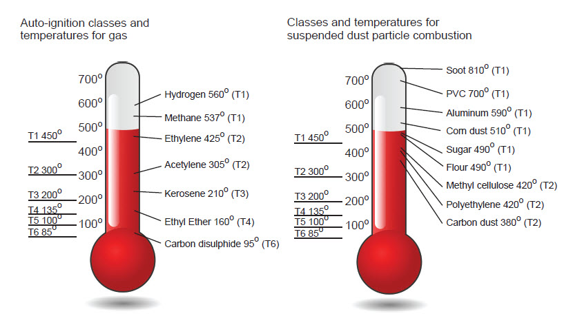
Design characteristics for explosion proof equipment (UL674 and ATEX)
There are various design criteria that the manufacturer can incorporate into their design. What is chosen will dictate the hazardous environment that the equipment can be used in. There are 4 “General Principles” of protection against explosion. They include:
• Explosion Containment – allows the explosion to occur but confines it to a defined area. A structure cannot fail from the explosion.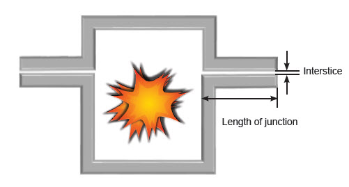
• Segregation – a method that attempts to separate or isolate the electrical parts from the explosive mixture. Practices include pressurization, encapsulation, oil immersion, and powder filling.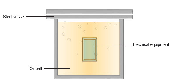
• Prevention – a method that limits the energy, both electrical and thermal, to safe levels under both normal and fault conditions. Practices include Increased Safety, Intrinsic Safety, Non-Incendive (simplified) and Special Protection.
• Increased Safety – must prevent the possibility of having excessive temperature or generations of arcs or sparks inside or outside the apparatus during normal operation. Accomplished by incorporating an elevated safety factor to all components that make up the apparatus (connections, wiring, the degree of protection of enclosure, etc.).
• Intrinsic – the most representative of the prevention concept and is based on the limitation of the energy stored in an electrical circuit (the circuit is incapable of generating arcs, sparks or combustible thermal effects). Intended for process instrumentation applications where the power required is less than 30 volts and 100 mA.
• Non-Incendive – similar to Intrinsic where the electrical apparatus is incapable of igniting a surrounding mixture during normal operation. They differ in that the non-incendive is not evaluated for safety under fault conditions, so as a result is not approved for Div. 1 environments.
• Special Protection – developed to allow certification of equipment that is not developed according to any of the existing protection methods. Can be considered safe for a specific hazardous location but must undergo appropriate tests and/or a detailed analysis of the design.
Safety first
 By helping operations personnel and engineers better understand the many factors that go into hazardous duty motor selection, the risk of explosions in facilities can be substantially reduced. Understanding the commonly used terms and design criteria used to qualify equipment provides facility managers with assurance that their operations are safe and in compliance with applicable regulations.
If you’re uncertain that your servo motor will be safe in the environment in which it must operate, always consult the motor manufacturer for assistance. Never guess when worker safety is at stake.
To keep this information on explosion proof motor classifications by hazardous locations handy, download our whitepaper.
Article contributed by Jeff Nazzaro, gearhead and motor product manager, Electromechanical & Drives, North America. Article originally posted on May 2, 2018 on Parker’s blog, blog.parker.com.